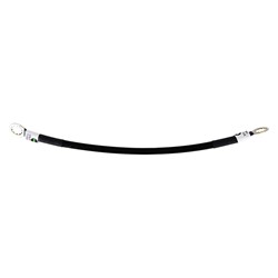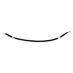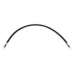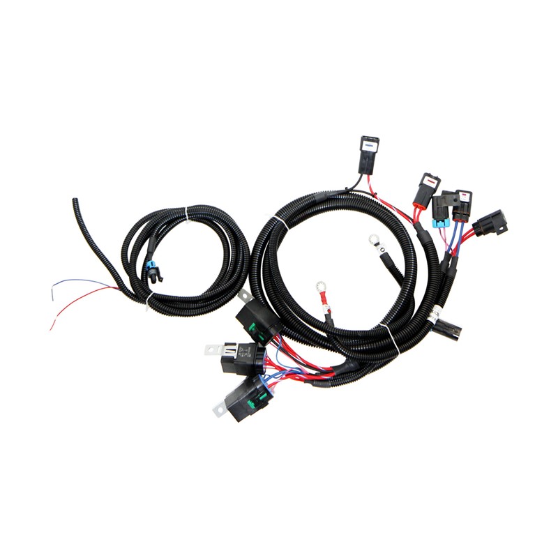

Dual Series / Parallel Fan harness HD
Quick Overview
- Two-speed operation — series/parallel switching gives true low and high fan speed
- Two-speed operation — series/parallel switching gives true low and high fan speed
- 30A continuous / 40A intermittent per circuit on 10AWG copper
- PCM-safe pull-to-ground triggers, approx. 100mA draw
- Weatherproof build with ultrasonically welded splices — no solder joints
Show More
$149.99
per EACH (USD)Dual Electric Fan Control Harness
Series / Parallel Two-Speed Operation — Heavy Duty 630 Series
Item #: FNWH-007
Product Overview
Many current OE and aftermarket dual fan assemblies draw upwards of 30 amps continuously. Factory fan circuits, relays and fusible links were never sized for that load, and running modern fans through them causes voltage drop, reduced airflow, melted relay terminals and eventual circuit failure.
The FNWH-007 pulls the fans off the factory circuit entirely and feeds them directly from the battery through 10-gauge wire and sealed high-current relays. The result is full system voltage at the fan motors, correct airflow at idle and in traffic, and no high-current load passing through vehicle wiring that was not designed to carry it.
How Two-Speed Operation Works
The harness has two small trigger wires — red and blue. Both are pull-to-ground inputs. Which of them you ground determines whether the fan motors are wired in series or in parallel, giving genuine two-speed operation without a fan controller or pulse-width module.
| Red Trigger | Blue Trigger | Fan Wiring | Result |
|---|---|---|---|
| Open | Open | — | Fans off |
| Open | Grounded | — | Fans off — not a valid control state |
| Grounded | Open | Series | Low speed, ˜6V per motor |
| Grounded | Grounded | Parallel | High speed, 12V per motor |
Blue is the mode selector, not a second speed input. Ground red for low speed, then add blue to step up to high speed. Blue should never be triggered on its own.
This mirrors the way many factory fan speed control systems operate, including LS1 applications. Low speed handles normal traffic and light load conditions quietly and with far less current draw; high speed comes in for sustained heat load.
Engineering Specifications
- Current Capacity: 40 amps intermittent and 30 amps continuous on each circuit, in the harshest environments.
- 10 Gauge Primary Circuits: Heavy-duty copper carries high fan loads with minimal voltage drop.
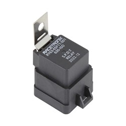
- 40A 630-Series Relays: Sealed heavy-duty relays with built-in EMI suppression.
- PCM-Safe Control: Relays are negative switched (pull-to-ground) and draw approximately 100mA (1/10 amp), safe for most engine management fan control outputs.
- Ultrasonically Welded Splices: Every splice is ultrasonically welded — no solder joints anywhere in the harness.
- Weatherproof Throughout: Sealed relays, sealed connectors and fused circuits for under-hood service.
- Installation Hardware Included: Complete mounting and termination hardware supplied.
- Battery Terminal Upgrade (optional): Battery nuts with accessory power taps and body ground upgrade.
Compatibility & Control Options
| Fan Compatibility | Any pair of matched 12V electric fan motors drawing up to 30A continuous / 40A intermittent each. |
| Control Input | Two small trigger wires, red and blue, driven by a simple switch, a stand-alone fan controller, or a PCM. Control outputs must be negative-going (pull-to-ground). |
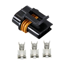
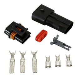
| Fan Connectors | Two Delphi 630-series connectors with terminals rated at 46 amps maximum, supplied loose for termination to your fan leads. |
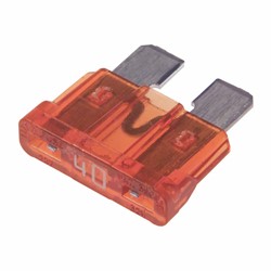
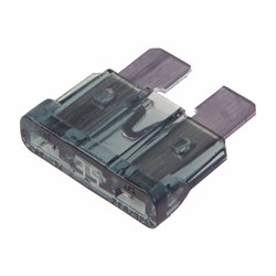
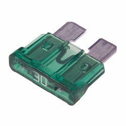
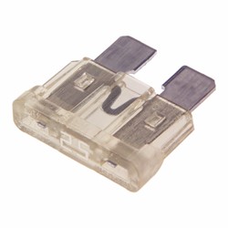
| Fusing | Ships pre-packed with 40-amp ATC fuses. Fuse to your actual measured load — see available ATC fuse ratings. |
Before You Install
Measure the actual current draw of your fans before selecting fuses. The supplied 40-amp fuses suit fans at the top of the harness rating; smaller fans should be fused accordingly to stay protected.
The two Delphi 630-series fan connectors are supplied with loose terminals so they can be matched to your specific fan leads. Termination is the installer's responsibility.
Frequently Asked Questions
Q: Can I connect this harness directly to my PCM fan outputs?
A: Yes, in most cases. The relays are negative switched and draw approximately 100mA with EMI suppression resistors built in, which is within the capability of most engine management fan control outputs. Confirm your PCM uses negative-going (pull-to-ground) outputs before wiring.
Q: Do I get low and high speed without a separate fan controller?
A: Yes. Speed is set by which trigger wires you ground. Grounding the red wire alone runs the fans in series at roughly 6 volts each for low speed; grounding red and blue together runs them in parallel at a full 12 volts each for high speed. No PWM module or external controller is required.
Q: Are the fan connectors pre-terminated?
A: No. The harness includes two Delphi 630-series connectors and terminals rated at 46 amps, supplied loose so they can be terminated to your specific fan leads. Basic crimping and soldering skills are required.
Q: Can I run fans that draw more than 30 amps continuously?
A: No. Each circuit is rated for 40 amps intermittent and 30 amps continuous. Exceeding the continuous rating will overheat the circuit regardless of fuse selection. Verify your fan draw under sustained load, not just inrush.
Q: Can I use this harness with two fans of different sizes?
A: Not recommended. Series operation divides supply voltage between the two motors, so mismatched fans will not share voltage evenly and low-speed performance will be unpredictable. Use matched fan motors.
Warranty & Support
Racetronix harnesses are considered the standard by which others are judged. Every harness is assembled using our computerized crimp-quality monitoring system and then circuit checked before it ships.
This harness is backed by our Limited Lifetime Warranty to the original purchaser while installed in the original vehicle. Warranty claims are subject to proper electrical diagnosis — part-swapping is not a substitute for troubleshooting.
How to get technical support
Racetronix provides technical support to verified customers through our support forum rather than by phone or email. Request access as soon as you place your order. Approval is handled while your parts are in transit, so the documentation and the people are already there on the day you start the install.
We concentrate support in one place for good reasons:
- Open around the clock. Answers do not wait for business hours or for someone to be free at a desk.
- Knowledge going back to 1999. Installation threads, schematics and diagnoses accumulated since we started, all searchable.
- Moderated and approval-only. No spam and no noise — just customers and our technical staff.
- No attachment limits. Post full-resolution photos of your own wiring and get an answer against what you are actually looking at, instead of a description of it.
- Answers stay available. A solution posted once helps the next person with the same vehicle.
© 2026 Racetronix. All rights reserved. Professional installation recommended.