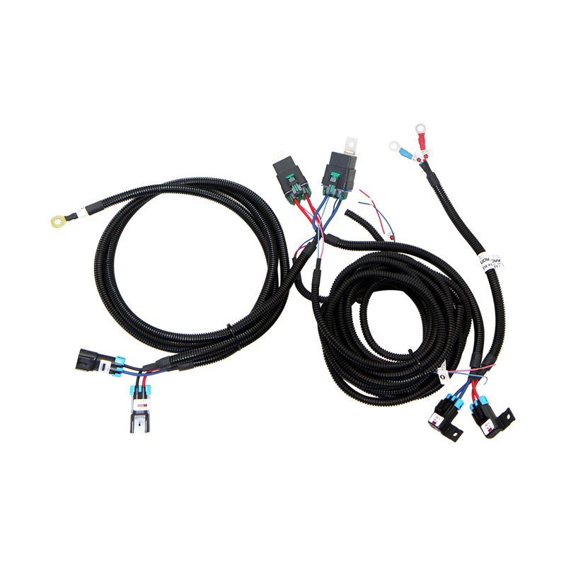

Uni High-Power Dual Fan Harness RY630
Quick Overview
- Pre-terminated output connectors — less crimping, ready to plug in
- 20A continuous / 30A max per circuit, set by the MP280 output connector
- Sealed 630-series relays and fuse holders on 10 AWG copper
- Isolated relay coils — switch the positive or ground side, PCM safe
- Final production run — replaced by the FNWK-004 kit
Show More
$119.99
per EACH (USD)Universal Dual Fan Harness — Pre-Terminated
Two Independent Circuits — 20 Amps Continuous, 30 Amps Maximum
Item #: FNWH-004HD
FNWH-004HD is being discontinued. Our FNWK-004 Universal Dual Fan Harness Kit replaces it, with 40-amp circuits and connectors you cut and terminate to your own vehicle's dimensions.
Product Overview
Modern electric fans pull serious current, and factory fan circuits were never sized for it. Running high-output fans through the original wiring, relays and fusible links costs you voltage at the motor, which costs you airflow — and eventually costs you a melted relay terminal.
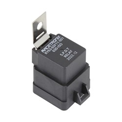
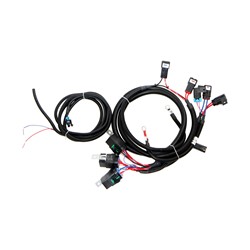
The FNWH-004HD takes both fans off the factory circuit and feeds them from the battery through 10-gauge copper, sealed 630-series relays and sealed 630-series fuse holders. Each fan gets its own fused, relayed, independently triggered circuit.
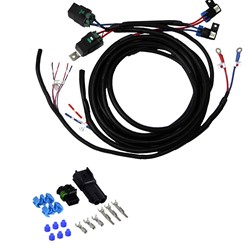
What sets this version apart is that the output connectors are already fitted. The harness arrives with both fan connectors crimped, sealed and looms in place. Cut the bag open, plug in the mating halves supplied in the installation kit, and wire your fans.
Pre-Terminated Outputs
Both output connectors are Metri-Pack 280 sealed two-way bodies, terminated at the factory on 10 AWG wire under our crimp-quality monitoring system. You terminate only the mating halves onto your own fan leads.
The Metri-Pack 280 output connector sets the ceiling on this harness, below what the 10-gauge wire, the 630-series relays and the 630-series fuse holders would otherwise carry. Size your fans to 20 amps continuous each, with 30 amps as a short-duration maximum.
Do not fit a larger fuse than supplied. Above these figures the connector, not the fuse, becomes the first thing to fail — and unlike a blown fuse, an overheating connector gives no warning.
If your fans draw more than 20 amps continuously — which covers most current high-output dual fan assemblies — use the FNWK-004 kit instead, which runs 46-amp Metri-Pack 630 connectors on 40-amp circuits.
Wire Identification
| Wire | Gauge | Function |
|---|---|---|
| Red | 10 AWG | Circuit 1 switched positive to fan connector |
| Blue | 10 AWG | Circuit 2 switched positive to fan connector |
| Black ×2 | 10 AWG | Fan negatives — from the two fan connectors to a shared chassis ring terminal |
| Red | 20 AWG | Circuit 1 relay coil positive |
| Pink | 20 AWG | Circuit 1 relay coil negative |
| Blue | 20 AWG | Circuit 2 relay coil positive |
| Light Blue | 20 AWG | Circuit 2 relay coil negative |
Nothing is commoned internally. Each relay coil has its own positive and its own negative, so you can switch either side: feed the coil positive and ground the negative through a switch, or hold the positive at +12V and let a PCM pull the negative to ground. The two circuits can run from different control sources.
How the fans are grounded
Each fan connector carries both sides of its circuit — the switched positive from its relay, and a 10 AWG black negative. The two black wires share a single ring terminal that bolts to the chassis near the fans: the frame on a body-on-frame vehicle, or a solid point on the unibody.
A fan drawing 30 amps returns 30 amps through that ring terminal. Paint, seam sealer, rust or a tired factory body-to-frame strap will cost you voltage at the motor exactly the way undersized positive wiring does, and it is the harder fault to find afterwards. Scrape to bare metal, use a star washer, and check the body-to-engine and body-to-frame bonds while you are there.
If those bonds are marginal, our BGC series body ground cables are listed in the add-ons below.
Harness Layout & Lengths
Because the outputs are pre-terminated, these lengths are fixed. Check them against your intended relay mounting position before ordering.
| Battery to fuse holders | 16" — 10 AWG red and blue, terminated in a 5/16" ring terminal |
| Fuse holders to relays | 18" — 10 AWG red and blue |
| Relays to fan connectors | 72" (6 ft) — 10 AWG red and blue |
| Fan connectors to chassis ground | 24" — 10 AWG black, two wires to a shared ring terminal |
| Relay coil positives | 144" (12 ft) — 20 AWG red and blue |
| Relay coil negatives | 96" (8 ft) — 20 AWG pink and light blue |
The entire harness is covered in high-temperature nylon split loom.
Engineering Specifications
- Two Independent Circuits: Separately fused, separately relayed and separately triggered, one per fan.
- 20 Amps Continuous, 30 Amps Maximum, Per Circuit: Limited by the Metri-Pack 280 output connector, not by the wire or relays.
- 10 Gauge Throughout: Heavy copper on both circuits and both grounds for minimal voltage drop under sustained load.
- Sealed 630-Series Relays: Shrouded, sealed relays rated for exposed under-hood environments.
- Sealed 630-Series Fuse Holders: Weather-sealed inline holders, fused and labelled to the connector rating.
- Fully Isolated Relay Coils: Both coil leads brought out on each circuit, so either side can be switched.
- PCM / ECM Safe: Internal suppression resistors and roughly 100mA coil draw, safe for solid-state engine management outputs.
- High-Temperature Nylon Loom: Full-length coverage on every branch of the harness.
- Pre-Terminated Outputs: Both fan connectors crimped and sealed under our computerized crimp-quality monitoring system.
What's Included
| Harness | FNWH-004HD, fully assembled with both output connectors fitted and fuses installed |
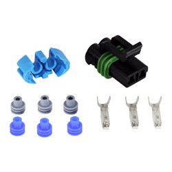
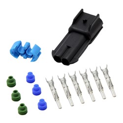
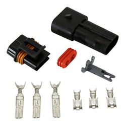
| Mating fan connectors | Two Metri-Pack 280 two-way female bodies with terminals and cable seals, for termination to your fan leads |
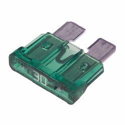
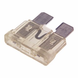
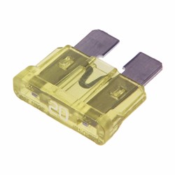
| Spare fuses | Two spare ATC fuses |
| Hardware | Self-tapping mounting screws, silicone dielectric compound, and nylon cable ties |
Upgrading to 40 Amps
If you want the full 40-amp capability the wire and relays are capable of, the output connectors can be replaced. This is an owner modification and requires cutting the factory-fitted connectors off.
- Cut off both Metri-Pack 280 output connectors and terminate two RCS-011 Metri-Pack 630 sets in their place, rated 46 amps on 10–12 AWG.
- Replace both 30-amp fuses with 40-amp ATC fuses.
- Change the fuse cap labels so they read 40 amps, not 30.
All three steps are needed. Fitting 630 connectors and leaving the 30-amp fuses in place will nuisance-blow on a hot day; changing the fuses without changing the labels leaves the next person to work on the car reading the wrong rating.
If you know in advance that you want 40-amp circuits, the FNWK-004 kit ships that way from the start and costs less than doing this conversion.
Before You Install
The harness end is done for you, but the mating connectors supplied in the installation kit ship with loose terminals so they can be matched to your fan leads. Proper B-type crimping tools are recommended.
Measure the sustained draw of each fan, not the inrush. Both fans should sit at or under 20 amps continuous, with 30 amps as a short-duration ceiling. Fans above that need the FNWK-004 kit.
Frequently Asked Questions
Q: Why is this rated 20 amps continuous when the wire and relays are good for 40?
A: The Metri-Pack 280 output connector is the limiting part. A circuit is only as good as its weakest link, so we rate and fuse the harness to the connector rather than to the wire. The upgrade section above covers converting to 40 amps if you need it.
Q: What is the difference between this and the FNWK-004 kit?
A: This harness arrives with the output connectors already fitted at set lengths, so there is less crimping to do. The kit ships the connectors loose, letting you cut every leg to suit your vehicle, and uses 46-amp Metri-Pack 630 connectors for a full 40 amps per circuit. This harness is being discontinued; the kit continues.
Q: Can I trigger this from my PCM or ECM?
A: Yes. The relays have internal suppression resistors and draw roughly 100mA, so no external resistor or diode is required. Hold the coil positive at +12V and let the PCM pull the coil negative to ground.
Q: Does this give me a low and a high fan speed?
A: Not per fan. Each circuit runs its fan at full voltage. You get staging — one fan or both — rather than two speeds from one fan. For true series/parallel two-speed operation from a pair of fans, see FNWH-007.
Q: Can I shorten the harness?
A: Not without cutting off the factory-fitted output connectors. The lengths listed above are fixed. If you need to size the runs to your own vehicle, the FNWK-004 kit is supplied unterminated for exactly that reason.
Warranty & Support
Racetronix harnesses are considered the standard by which others are judged. Every harness is assembled using our computerized crimp-quality monitoring system and then circuit checked before it ships.
This harness is backed by our Limited Lifetime Warranty to the original purchaser while installed in the original vehicle. Warranty claims are subject to proper electrical diagnosis — part-swapping is not a substitute for troubleshooting.
How to get technical support
Racetronix provides technical support to verified customers through our support forum rather than by phone or email. Request access as soon as you place your order. Approval is handled while your parts are in transit, so the documentation and the people are already there on the day you start the install.
We concentrate support in one place for good reasons:
- Open around the clock. Answers do not wait for business hours or for someone to be free at a desk.
- Knowledge going back to 1999. Installation threads, schematics and diagnoses accumulated since we started, all searchable.
- Moderated and approval-only. No spam and no noise — just customers and our technical staff.
- No attachment limits. Post full-resolution photos of your own wiring and get an answer against what you are actually looking at, instead of a description of it.
- Answers stay available. A solution posted once helps the next person with the same vehicle.
© 2026 Racetronix. All rights reserved. Professional installation recommended.