
Relay 280-ISO Sealed S.P.D.T. 12VDC 30/30A
$10.00
per EACH (USD)280-ISO Sealed Automotive Relay, SPDT (1 Form C), 12 VDC
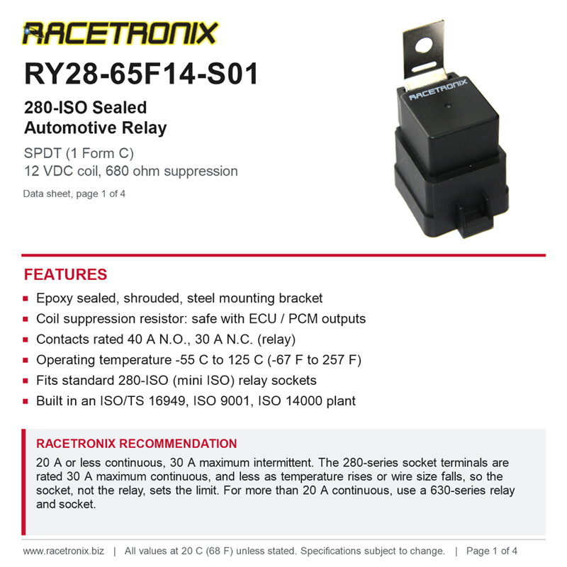
Sealed, shrouded, with steel mounting bracket and coil suppression resistor. Used in most current-production Racetronix harnesses.
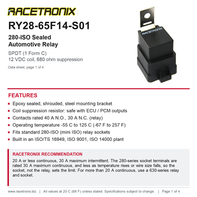
The Racetronix RY28-65F14-S01 is a 12 volt, single pole double throw (SPDT, 1 Form C) relay in the standard 280-ISO (mini ISO) footprint. When the coil is off, terminal 30 is connected to 87a (normally closed). When the coil is energized, 30 switches over to 87 (normally open). That lets one relay turn a load on, turn a load off, or switch power between two circuits.
The cover is sealed against moisture and dirt, and a plastic shroud with a steel mounting bracket protects the terminals and lets you bolt the relay down. A 680 ohm resistor across the coil absorbs the voltage spike when the coil turns off, so the relay is safe to drive from a computer, an engine controller or another solid-state output. This is the relay used in most current-production Racetronix harnesses, and it is the direct replacement for the relay in our older hotwire kits.
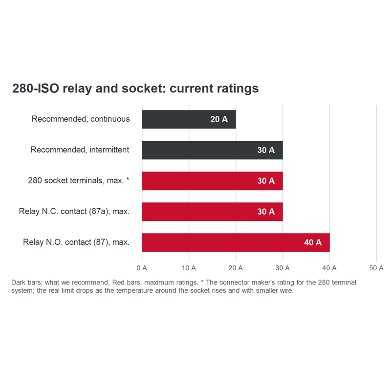
We recommend continuous loads of 20 amps or less, and intermittent loads of no more than 30 amps. The maximum ratings below are the contact limits under test conditions; real-world heat, wire size and connector contact all add up, and a relay run well below its limit lasts far longer. The questions at the bottom of this page explain how heat, wire size and mounting location change the safe current. For loads of more than 20 amps continuous, such as a high-flow fuel pump or a large electric fan, use one of our 630-series relays and sockets (RYCS-009 or RYCS-010).
Key features
- SPDT (1 Form C): one normally open (87) and one normally closed (87a) contact, switched from common terminal 30.
- 12 VDC coil with a 680 ohm, 1/2 watt suppression resistor in parallel: safe with ECU, PCM and other solid-state drivers.
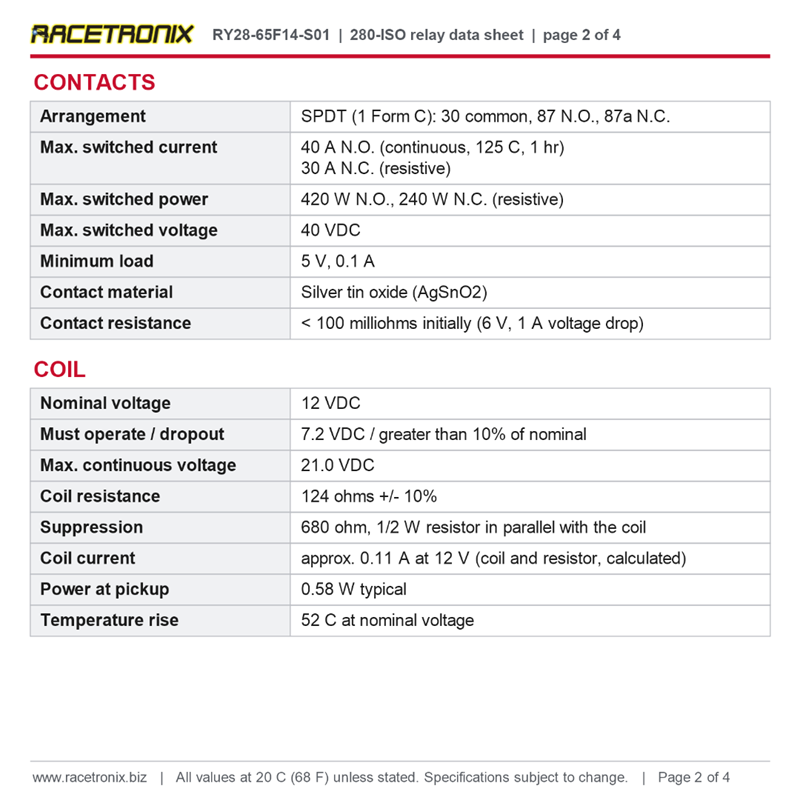
- Maximum switched current: 40 A normally open, 30 A normally closed (resistive). Recommended: 20 A continuous, 30 A intermittent.
- Epoxy sealed plastic cover, shrouded, with a steel mounting bracket.
- Operating temperature -55°C to 125°C (-67°F to 257°F): fine under the hood.
- Silver tin oxide contacts; tinned copper alloy 0.110" (2.8 mm) quick-connect terminals.
- P.B.T. polyester enclosure.
- Built in an ISO/TS 16949, ISO 9001 and ISO 14000 certified plant.
- Fits standard 280-ISO (mini ISO) relay sockets, such as our RYCS-005 SPDT socket kit.
Terminals: what each one does
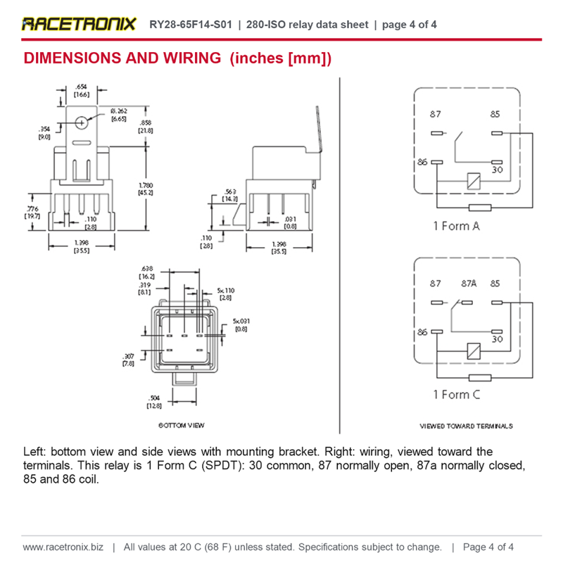
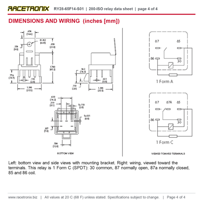
The terminal numbers are moulded into the relay base. These are the standard ISO automotive relay numbers, so they match most wiring diagrams.
| Terminal | Function | Connects to | Typical wire |
|---|---|---|---|
| 30 | Common (switched contact) | Battery positive, through a fuse or circuit breaker sized for the load | Heaviest wire in the circuit |
| 87 | Normally open (N.O.) | The load you want turned on when the coil is energized | Same gauge as terminal 30 |
| 87a | Normally closed (N.C.) | The load you want on while the coil is off, or left empty if not used | Sized for its own load |
| 85 | Coil | Switched trigger (positive) or ground; the resistor is not polarity sensitive | Light gauge (coil draws about 0.11 A) |
| 86 | Coil | The other side of the trigger circuit (ground or positive) | Light gauge |
When the coil is off: 30 is connected to 87a. When the coil is energized: 30 is connected to 87, and 87a is open. If you only need an on/off switch, wire 30 and 87 and leave 87a empty; the relay then works like a single pole (SPST) relay.

Dimensions in inches [mm], bottom view and wiring diagram. This relay is the 1 Form C (SPDT) version, with terminal 87A.
Specifications
General
| Part number | RY28-65F14-S01 |
| Type | 280-ISO (mini ISO) automotive relay |
| Contact form | SPDT, single pole double throw (1 Form C) |
| Cover | Plastic dust cover, shrouded, steel mounting bracket, epoxy sealed |
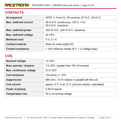
| Coil suppression | 680 ohm, 1/2 watt resistor in parallel with the coil |
| Enclosure | P.B.T. polyester |
| Terminals | Tinned copper alloy, 0.110" (2.8 mm) quick connect |
| Weight | 41 grams (shrouded version) |
Coil
| Nominal voltage | 12 VDC |
| Must operate voltage | 7.2 VDC (the relay may pull in below this) |
| Dropout voltage | Greater than 10% of nominal coil voltage |
| Maximum continuous voltage | 21.0 VDC |
| Coil resistance | 124 ohms ± 10% |
| Combined resistance with the 680 ohm resistor | About 105 ohms (calculated) |
| Coil current | About 0.11 A at 12 V, 0.13 A at 13.5 V (calculated) |
| Coil power at pickup | 0.58 W (typical) |
| Maximum continuous dissipation | 3.7 W at 20°C (68°F) |
| Coil temperature rise | 52°C (94°F) at nominal voltage |
| Maximum coil temperature | 180°C (356°F) |
Contacts
| Arrangement | SPDT (1 Form C): common 30, normally open 87, normally closed 87a |
| Material | Silver tin oxide (AgSnO2) |
| Maximum switched current (resistive) | 40 A normally open (continuous at 125°C, 1 hour); 30 A normally closed |
| Maximum switched power (resistive) | 420 W normally open; 240 W normally closed |
| Maximum switched voltage | 40 VDC (above 30 VDC needs special precautions) |
| Minimum load | 5 V, 0.1 A |
| Contact resistance | Less than 100 milliohms when new (6 V, 1 A voltage drop method) |
| Racetronix recommendation | 20 A or less continuous; 30 A maximum intermittent |
Timing, insulation and environment
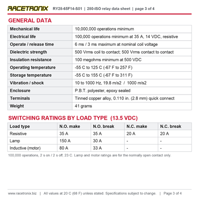
| Operate time | 6 ms maximum at nominal coil voltage |
| Release time | 3 ms maximum at nominal coil voltage |
| Dielectric strength | 500 Vrms coil to contact; 500 Vrms contact to contact (at sea level, 1 minute) |
| Insulation resistance | 100 megohms minimum at 500 VDC, 20°C, 50% RH |
| Operating temperature | -55°C to 125°C (-67°F to 257°F) |
| Storage temperature | -55°C to 155°C (-67°F to 311°F) |
| Vibration | 10 to 1000 Hz, 19.8 m/s² |
| Shock | 1000 m/s² |
| Mechanical life | 10,000,000 operations minimum |
| Electrical life | 100,000 operations minimum at 35 A, 14 VDC, resistive load |
All values at 20°C (68°F) unless stated.
Load ratings by load type
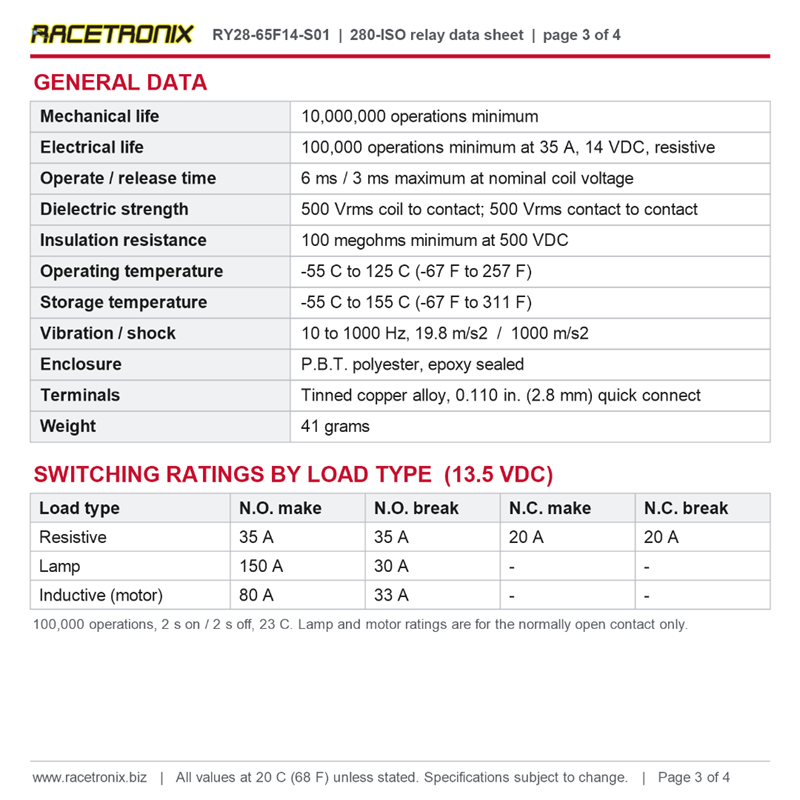
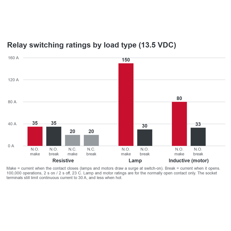
Switching ratings at 13.5 VDC and 23°C, tested for 100,000 operations at 2 seconds on, 2 seconds off. Lamps and motors draw a surge when they switch on (make), which is why the make rating is higher than the break rating for those loads. Ratings are for a relay without a diode across the coil.
| Load type | Normally open (87): make | Normally open (87): break | Normally closed (87a): make | Normally closed (87a): break | Example loads |
|---|---|---|---|---|---|
| Resistive | 35 A | 35 A | 20 A | 20 A | Heaters, glow plugs, resistive elements |
| Lamp | 150 A | 30 A | — | — | Headlights, light bars (filament inrush) |
| Inductive | 80 A | 33 A | — | — | Fuel pumps, fans, motors, solenoids |
Lamp and inductive ratings are published for the normally open contact only.
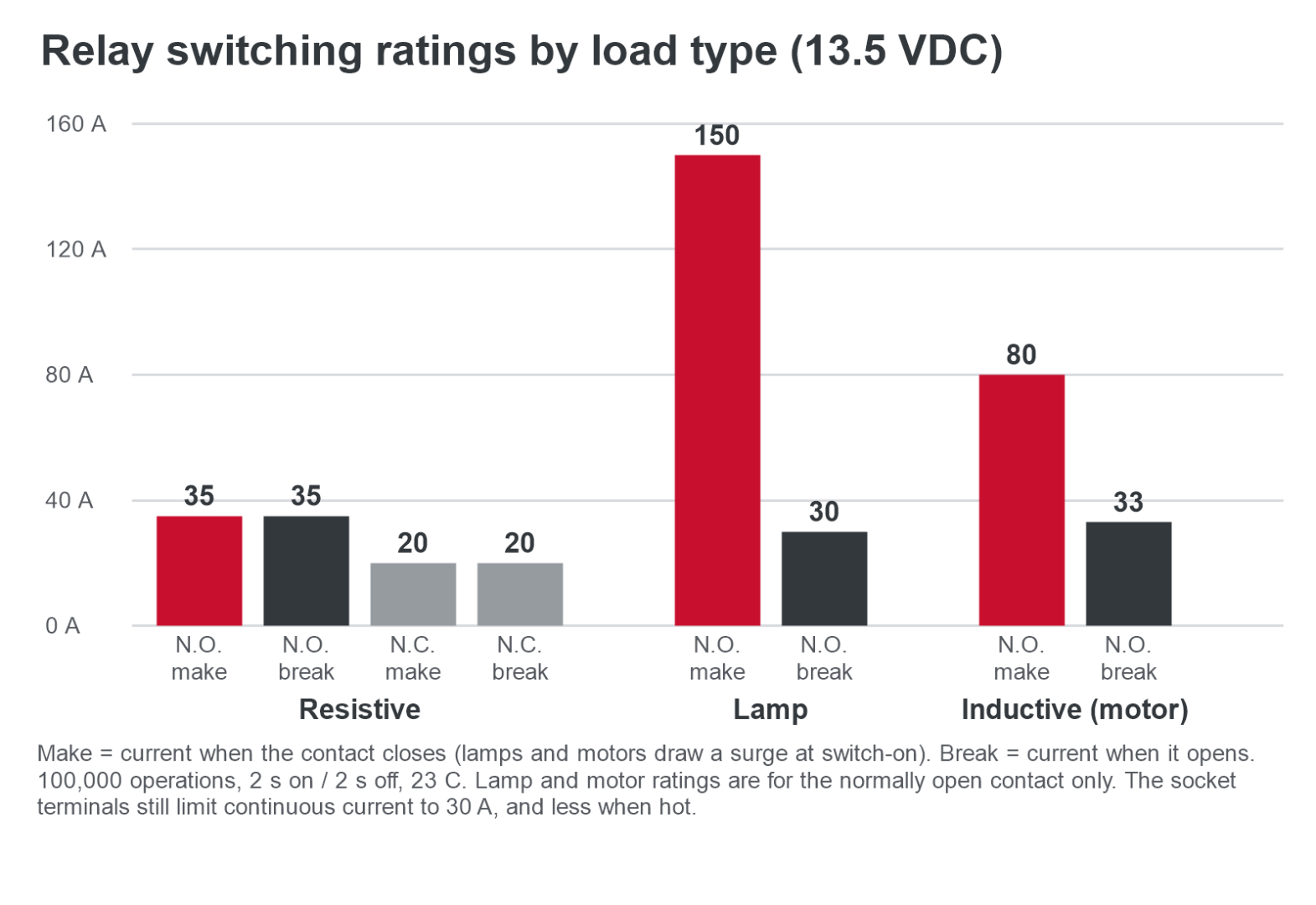
Switching ratings by load type. Lamp and motor loads draw a surge when they switch on (make).
Dimensions
| Measurement | Inches | Millimetres |
|---|---|---|
| Body width (across the shroud) | 1.397" | 35.5 |
| Overall height, including bracket | 1.78" | 45.2 |
| Shroud height | 0.776" | 19.7 |
| Mounting bracket width | 0.655" | 16.6 |
| Mounting hole diameter | 0.262" | 6.65 |
| Terminal length | 0.433" | 11.0 |
| Terminal width x thickness | 0.110" x 0.032" | 2.8 x 0.8 |
Tolerance ±0.010" unless shown otherwise on the drawing.
Sockets and related parts
- RYCS-005: SPDT relay connector kit (280-ISO, 5 terminals) for this relay.
- RYCS-001: SPST relay connector kit (280-ISO, 4 terminals). This relay also fits it; terminal 87a is then unused.
- RYCS-009 and RYCS-010: 630-series SPDT relay connector kits, for loads above 20 A continuous. 630-series relays need their own socket and terminals; they do not plug into a 280 socket.
Frequently asked questions
The relay is rated 40 A. Why do you recommend 20 A continuous?
A current rating is really a heat rating. Every contact, crimp and terminal has a tiny electrical resistance, and current flowing through resistance makes heat. The heat goes up with the square of the current: double the current and you get four times the heat in every connection.
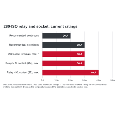
The relay's contacts are rated to 40 A (normally open) under test conditions, but the current also has to pass through the socket terminals. The connector maker rates the 280 terminal system at 30 A maximum continuous, and its test figures are for a single terminal in free air on heavy wire. In a real relay socket, two or three loaded terminals sit side by side, right next to a relay coil that runs warm, often under the hood. Each of those things lowers the current a terminal can carry before it overheats.
That is why we recommend 20 A continuous: it leaves margin for heat, vibration, ageing and a less-than-perfect crimp. Up to 30 A intermittent is fine for short bursts, because the parts do not have time to reach full temperature. For more than 20 A continuous, use a 630-series relay and socket (RYCS-009 or RYCS-010), whose larger terminals are rated 46 A.
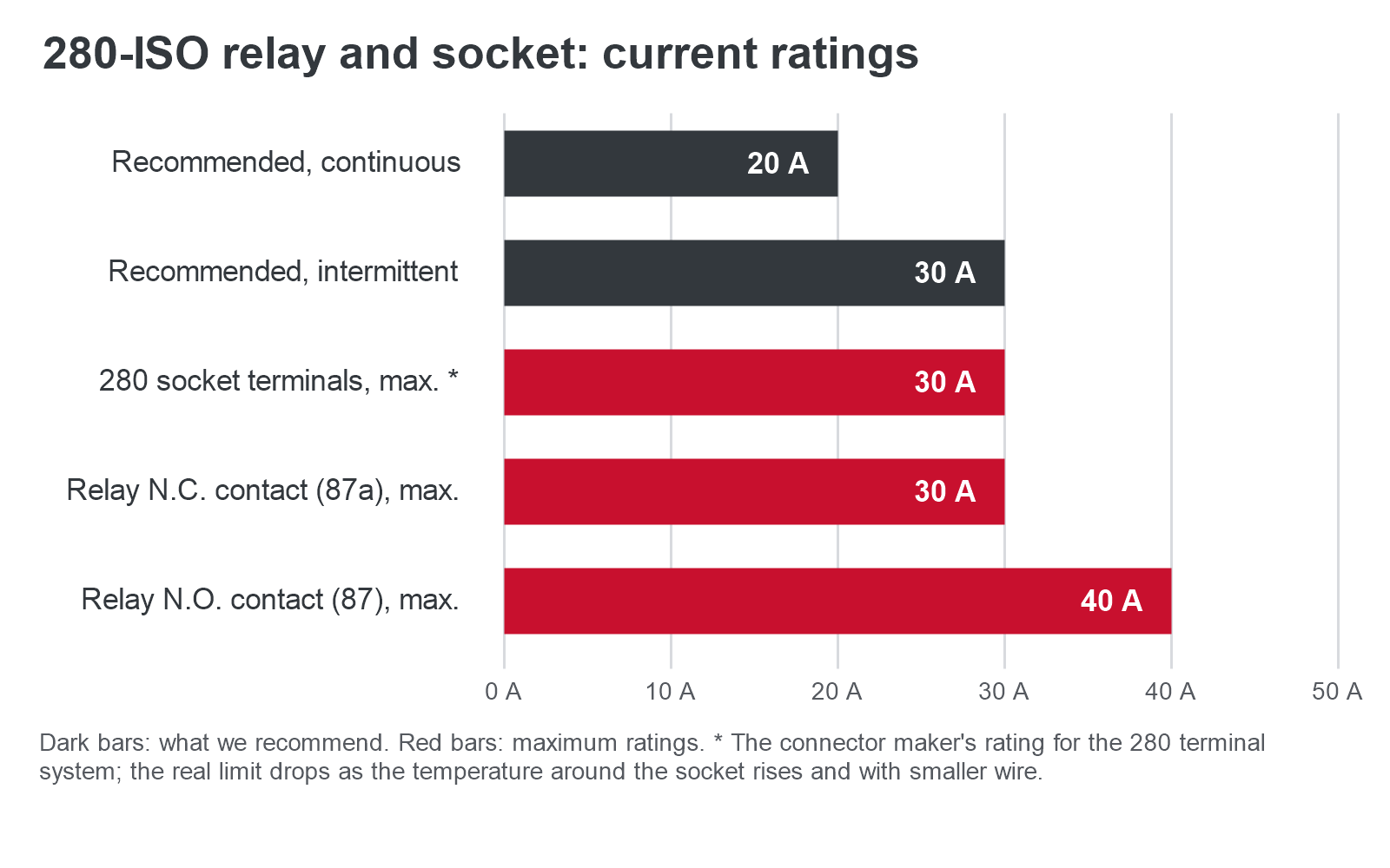
Our recommendation (dark) against the maximum ratings (red). The kit is limited by the socket terminals, not the relay.
How does temperature change the rating?
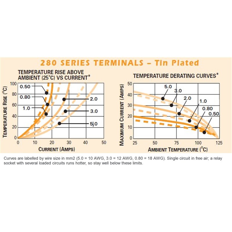
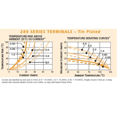
The terminals and the socket plastic are rated to 125°C. Current heats the terminal above the temperature of the air around it, so the hotter the surroundings, the less room is left for heat from current. At 125°C ambient there is no room left at all. This is called derating, and the connector maker publishes curves for it.
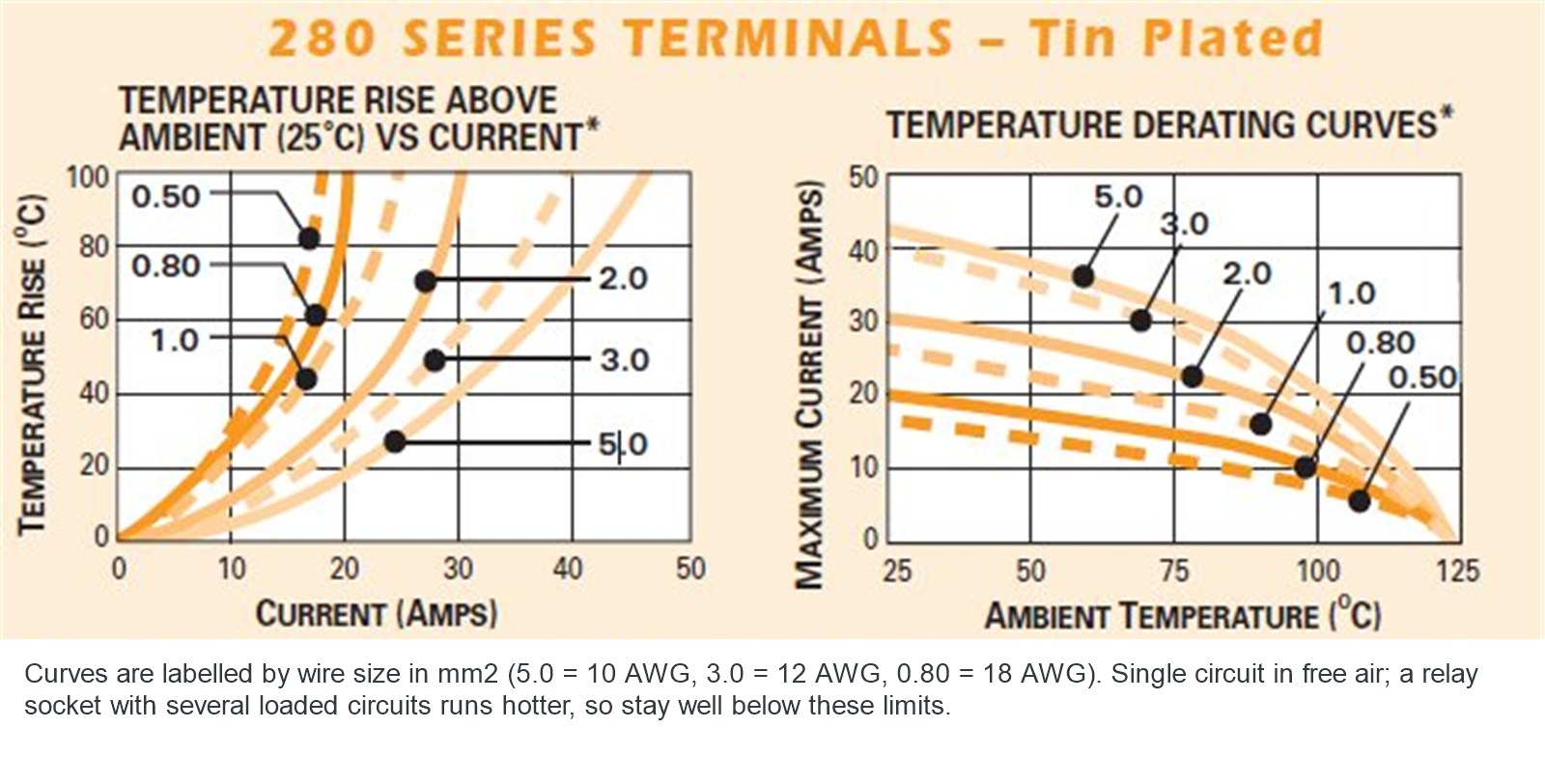
Left: how far a terminal heats above the air around it at a given current. Right: the most current it can carry at a given air temperature. Curves are labelled by wire size in mm².
Read from those curves, approximately, for one terminal in free air:
| Wire on the terminal | 25°C (77°F) | 50°C (122°F) | 75°C (167°F) | 100°C (212°F) |
|---|---|---|---|---|
| 10 AWG (5.0 mm²) | about 42 A | about 39 A | about 32 A | about 20 A |
| 12 AWG (3.0 mm²) | about 40 A | about 36 A | about 29 A | about 17 A |
| 18 AWG (0.8 mm²) | about 20 A | about 18 A | about 15 A | about 10 A |
A relay socket is not one terminal in free air, so real limits are lower than the table. On top of that, the relay's own coil runs about 52°C above the surrounding air when it is energized, and that heat sits right beside the terminals.
Why does the wire size matter?
The wire is the terminal's heat sink. Copper carries heat as well as current, so a heavy wire draws heat away from the crimp and the terminal, and it makes less heat of its own because it has less resistance per foot. The same terminal crimped on 10 gauge wire can carry noticeably more current than on 12 gauge, and much more than on 18 gauge (see the table above).
So: use 10 gauge wire on terminals 30 and 87 for loads near the top of the range, keep long runs as short as you can (long wire also costs voltage at the load), and make every connection properly. A loose, under-crimped or corroded crimp has extra resistance and becomes a hot spot even at moderate current, and it is a common cause of melted relay sockets.
Where should I mount the relay?
Somewhere cool and dry. Under the hood, right beside the engine or exhaust, the air can reach about 100°C (212°F), and at that temperature even a 10 gauge terminal is only good for about 20 A in free air. Inside the car, in the trunk, or under the car away from the exhaust, the air stays far cooler and the same relay and socket have much more headroom.
If it has to go under the hood, mount it on the inner fender or firewall, away from the exhaust manifolds and turbo, with the terminals facing down so water cannot sit on the seals.
Is it safe to trigger from an ECU or PCM?
Yes. The 680 ohm resistor across the coil absorbs the spike when the coil turns off, which protects solid-state outputs. The coil draws only about 0.11 A at 12 V.
Does coil polarity matter?
No. The suppression is a resistor, not a diode, so terminals 85 and 86 can be wired either way round.
What is the difference between SPDT and SPST?
An SPDT relay has a fifth terminal, 87a, that is connected to 30 while the coil is off. An SPST relay has only 87. If you do not need 87a, leave it empty and this relay works as an SPST relay.
Will it fit my older Racetronix hotwire kit?
Yes. This is the direct replacement for the 280-series relay in our older hotwire kits. The part number is printed on top of the relay you have; if it is a 630-series relay (RY63), it needs a 630 socket instead.
Is it waterproof?
The relay is sealed against moisture and dust. No IP rating is published, so mount it where it is not sprayed directly or sitting in water, with the terminals facing down.
Does it work on a 24 volt system?
No. This is a 12 V relay; its coil is rated for 21 VDC maximum continuous.
Questions and support
Not sure which relay your build needs? Email [email protected] before you order.
Racetronix provides technical support to verified customers through our support forum, not by phone or email. Please request forum access when you place your order so your account is approved before your parts arrive. The forum is moderated, open 24/7, and holds a knowledge base going back to 1999.